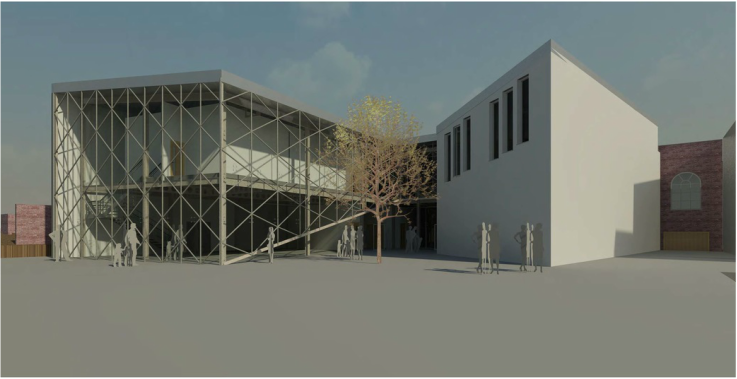
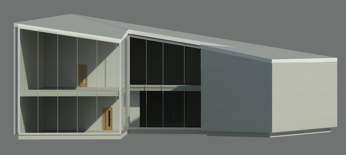
Render of final Revit model..
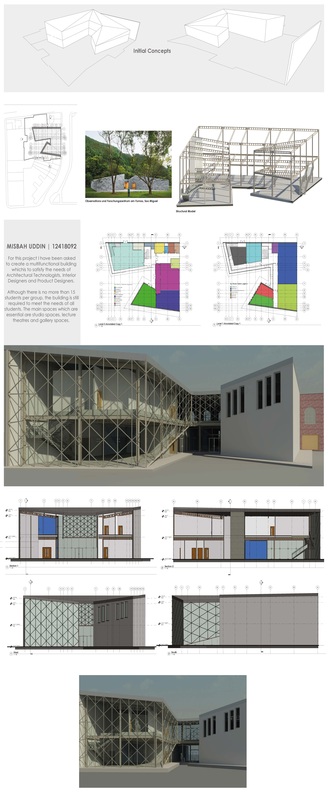
Design Project Portfolio..
Where to begin with the conclusion of this project?
|
Render of final Revit model.. Design Project Portfolio.. Where to begin with the conclusion of this project?
0 Comments
 For the last couple of months I've been saying how far behind I am with my design project however it's now time for our final design presentation and I've tried to play catch-up so I'm able to actually present something for the presentation.
First things first I didn't sleep the day before due to our Revit submission, so I ended up falling asleep very early having done nothing for my final pin-up. Luckily I managed to wake up fairly early on the day of our presentation got all dressed up (as I wanted to make some form effort) and rushed to University. With two hours before the presentations start I started preparing my presentation. In all honesty I'm surprised I managed to get anything on to the page however two hours later I managed to fill my A3's with my work (you don't understand how relieved I was) so I managed to print it and then began the presentations! I was really nervous about the presentations mainly because we had three guest critics one of whom was from Leeds university, another person from a practice from London and Sabeen who teaches on the Master degree at our university. The other reason why I was nervous was because when looking around the classroom there was some real amazing work from my peers. However in the end the presentation didn't actually go that bad instead it went much better than I thought it would. Some of the improvements I was asked to make were: - Include context throughout my drawings - Work on my render/selling image - Workout how exactly I'm incorporating the slope throughout my design - Create elevations and sections through just the use of lines - Ensure section includes the basic principles - Produce an environmental strategy So now we've got a week to produce our 120 pages design project portfolio, so I best get cracking! 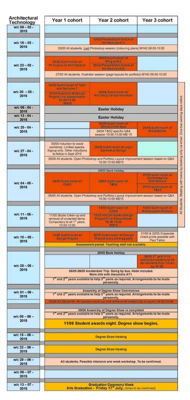 So we've been given a final timetable for all of our submissions as you can it is quite intense to say the least! In terms of submissions we do have the most compared to the other two years but after talking to the third years I can definitely say they have very tough work to produce as well!
However all I can say these next couple of weeks will be incredibly tough but it will definitely be rewarding, anyways as you can see I have to submit this blog in a few days so I best start getting posting! :) Overall I was regretting this pin-up because I did feel like I didn't have enough time to produce a decent amount of work because I've fallen behind quiet a bit. However I did manage to get there in the end, and really it went a lot better than I though it would, some improvements mentioned by Peter and James (Course Leader of 3D Design):
- The spans of my glulam beams could be longer, and glulam is a lot more effective in aesthetics when the depth is really big so try spanning with 10 meters - Work more on the sectional drawing - Connect precedent more to design project - Figure out roof design - Try and keep things simple and dramatic - Connect the 2 studio flats with the main building, maybe partially underground - Work with the slop of the site - Produce structural model These were the main improvements which I was asked to work on, and hopefully I can make them pretty soon whilst I have a few ideas in my mind. So this week I've been trying to work hard as we have a pin up presentation this Friday and as I haven't actually produced enough work I've been working hard to try and produce a decent amount. 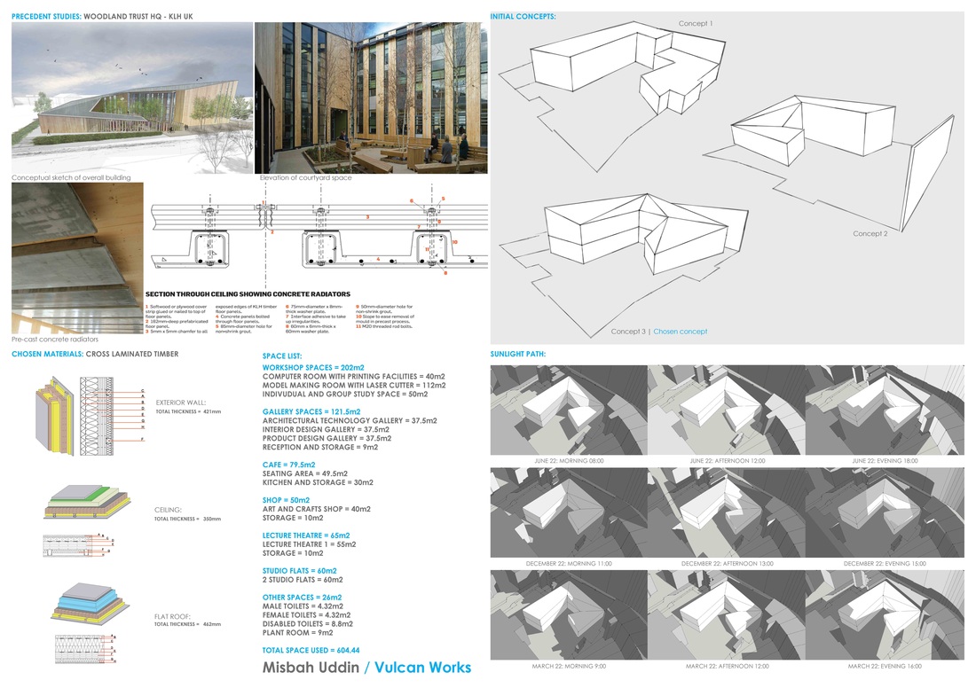
So i decided to base the first A1 around the research side of the project, so for example I included my precedents, chosen materials, initial concepts and sunlight data. 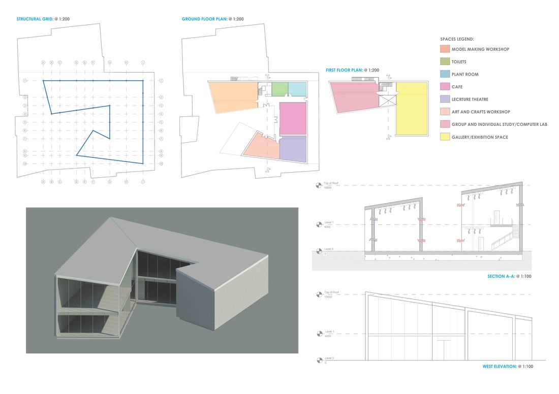
This A1 was based around the overall design of my concept, I included floor plans, elevations, sections and a 3D Model.
 Revit model continued.. As I have a pin-up this Friday I decided to try and complete my Revit model so I'm able to produce a few renders to include within my A1 sheet, to help my colleagues and those viewing understand the overall form I'm wanting for my building.
In all honesty there wasn't much to do however I did come across a few problems with the roof of my model, the main reason was because it sloped at different angles and in different positions. So I did end up spending a few more hours trying to figure out how I could do this within Revit. A few hours later I did manage to produce a roof (shown in image above) and this was the furthest I could get. I didn't really want to spend too much time as I have loads of other work to do to for my pin-up. However once I do have time I will pend it trying to fix the roof and completing the rest of the model. I also made a few changes to the South elevation, I created a curtain wall system which I wanted as this would allow natural light to penetrate through the workshop areas. 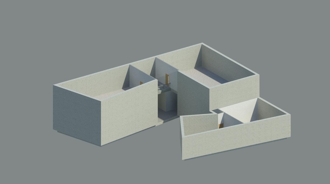 Revit model of design.. So today I finally started to use Revit to create my 3D model, as I know have plans to work from and finally figured what kind of form I'm wanting. Revit was introduced to us this year, and has been a really interest software. I'm used to creating 3D models using Sketchup, but I thought this would be a great opportunity to getting to know Revit.
I also went and spoke to Peter today, and he made me do a quick presentation in front of the 1st years, it was funny because I told Peter that I didn't have much to show however he still put me on the spotlight. However it wasn't as bad as I first thought it would be, however it was difficult to understand whether or not the first years was actually impressed with it. I think some people did like it, but because it's not completed I don't think everyone saw the overall vision for the form of the building. But I enjoyed using it in all honesty the way I feel about new software is: you can;t be really good at it unless you put the practice in, with this particular task I did enjoy it. 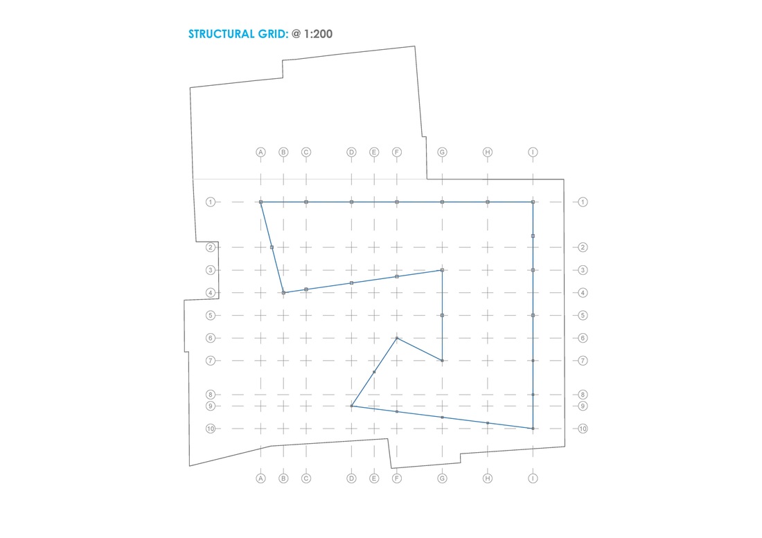 For my framed structure I wanted to use Glulam columns and beams, the main reason being because I wanted to try this method as I haven't previously used it.
- A structural grid of 5 x 5 meters - Columns where the building will be at 2 stories, they are: 350 x 350 mm columns - Columns where the building is only 1 story, 300 x 300 mm columns 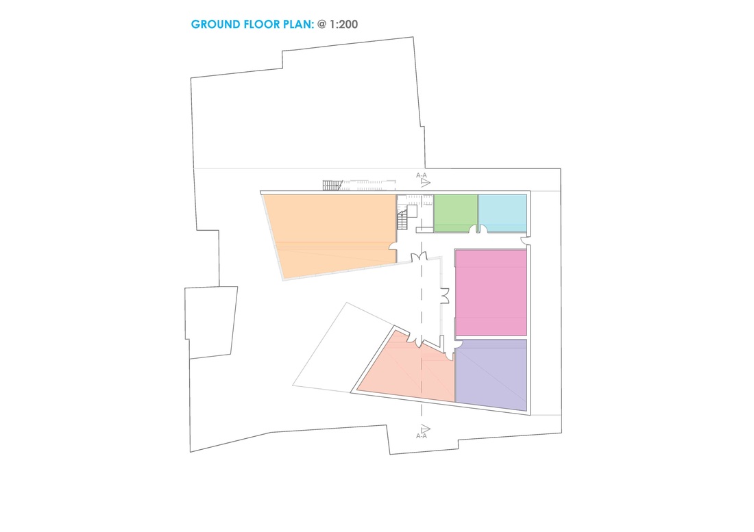 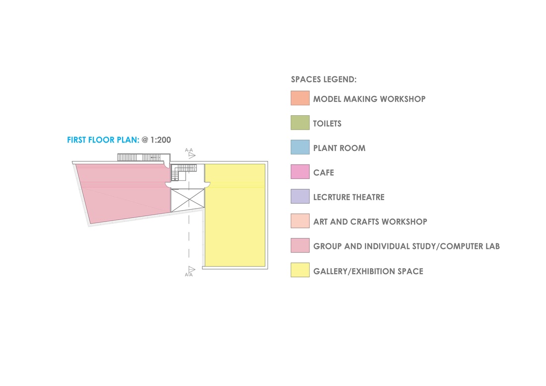 So after talking to Peter a couple of weeks ago and now I have managed to find the time, I made the following improvements:
- The toilets have been moved and switched with plant room and now they are both in a better position - Cafe walls have been opened up to allow for flowing space and flexibility - Fire exit and corridor has been introduced to Ground floor - Fire exit and stairs have been introduced for first floor as it didn't meet regulations - Changed staircase and lift design have been changed to meet building regulations, but also ensuring there's no wastage of space - A void has been introduced on first floor allowing more light to penetrate through to Ground floor. So today we went to London to go and visit the new Camden Borough Council building (Five Pancras Square). Although it is the headquarters for Camden Borough Council, it also includes a public leisure facility, which includes a public library, cafe, gym, swimming pool.
London’s King’s Cross has seen a surge of redevelopment in recent years, the most iconic of which – John McAslan + Partner’s new concourse for King’s Cross Station – was completed last year. The area has also been defined by the new Central Saint Martin’s campus, designed by Stirling Prize winner Stanton Williams, and Google’s new London headquarters. Plans have now been unveiled for Gridiron (One St. Pancras Square), a 50,000 square foot office building nestled between St. Pancras International and King’s Cross Stations, designed by David Chipperfield Architects and set for completion in the first half of 2014. (Extract taken from: http://www.archdaily.com/438007/gridiron-one-st-pancras-square-david-chipperfield/) - 14 Floors in total - Awarded BREEAM rating of 'Outstanding' - Connected to King's Cross (CHP) Energy Centre which helps provide low carbon heating and electricity - They achieved very high standards of environmental awareness during the construction process - Used responsibly sourced materials - Steps taken to maximize daylight factors throughout the building to minimize artificial lighting - Extensive sub-metering throughout the building to ensure energy and water use is monitored - Photo-voltaic Panels to achieve zero carbon status - A strong emphasis on passive design solutions Overall it is a very impressive building mainly down to how its been designed and maintained. For example they have a really big plant room which is the engine to driving the building. A lot of technologies were introduced for example PV panels on the elevations. This is a great building for us to use as inspiration for our own design projects as it does make good use of passive systems. To find out further information please check out: http://www.breeam.org/page.jsp?id=584 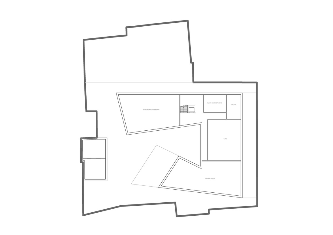 Ground Floor Plan.. 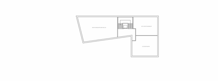 First Floor Plan.. So this is my 2nd attempt at drawing up floors plans for my design as the 1st time it went completely wrong and there wasn't anyway in trying to save it. However this time I did have much better as you can see from the drawings above.
So I managed to keep the workshops in the best location as this will ensure enough natural light will be able to penetrate these big spaces. So after speaking to Peter it was clear that the spaces needed a bit more work on them for example: - Toilets are in a bad position - Cafe walls need to be more open and flexible - No Fire exists on ground or first floor So overall these were the main changes as far as I can remember, so I best start making these improvements :) 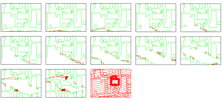 CAD document showing all sheets of A1 to be cut out using the Laser Cutter.. 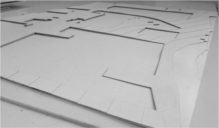 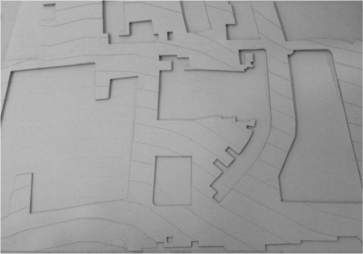 Site for 1st Model finsihed.. As a class we were asked to create a group site model of Vulcan Works at a scale of 1:250, which was to include the typography and surrounding buildings of the site. Myself and another class mate, Kendra took the responsibility of producing this model along with class.
Most of the time was spent on preparing the CAD work for the paper to be cut through the use of a Laser Cutter. The CAD was divided by me and Kendra, Kendra took the task of engraving and I took the task for all the cutting and placing the overall drawing on the sheets of A1. So we did end up using Cartridge paper for this model and we thought everything was going smoothly however until at the end we reaslised in the end that the in fact the spacing between the contour lines was in fact incorrect, meaning they wasn't to scale. Although its the worst thing anyone could say to us, as a group we was still pleased with the outcome. 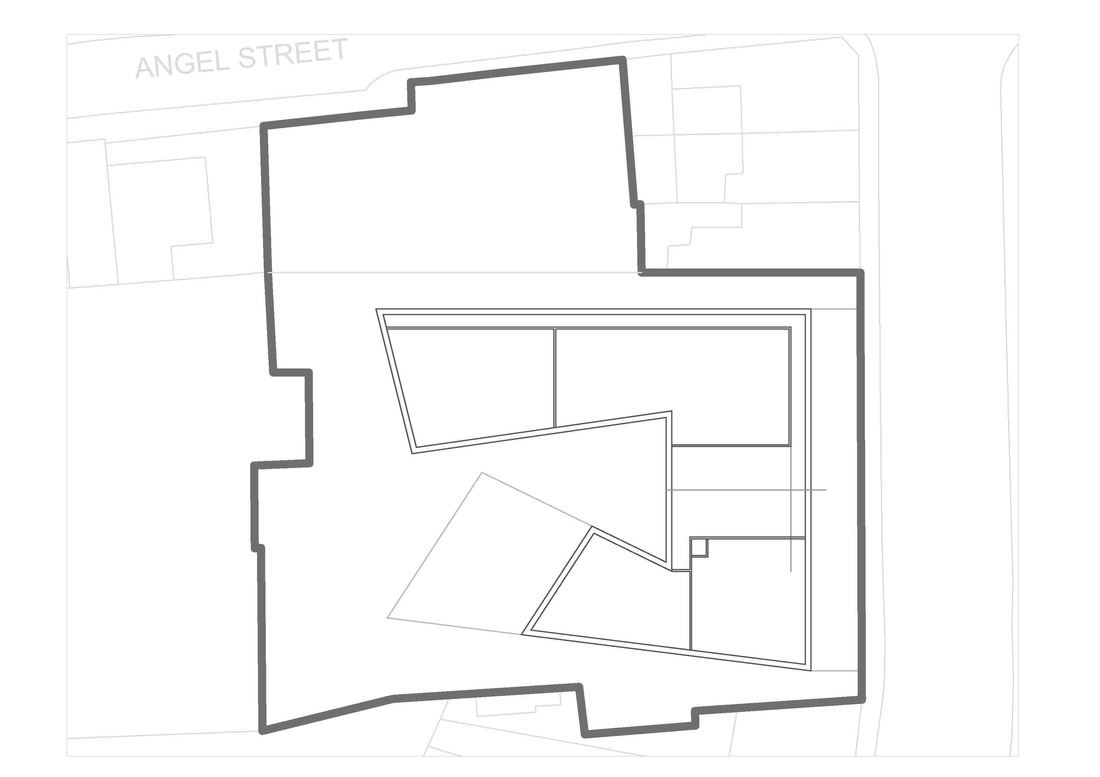 So this was my first attempt at trying separate spaces within the building to form the rooms which I wanted. You can tell it doesn't look right and that's because I realised after spending some time on it that it, and decided to stop because I was wasting my time and didn't want to waste my time even more. It was actually quite difficult trying to get my head around in trying to arrange the different rooms, but hopefully I'll have better luck at the next attempt.
So after talking with Peter we both decided that I would develop Concept 1 and 3, as I've already created the 3D mass model through the use of Sketchup. I had to create the surrounding buildings and then set-up the Geo-location on skecthup to ensure that the sunlight is accurate I set it up to the location of Vulcan Works. I wanted to compare sun light data for summer, winter and spring, for morning, afternoon and evening. So after setting the settings to those time intervals I exported the model to JPEG to give me an image for each interval. I then edited the data using Photoshop, by layer them for different season intervals meaning I combined morning, afternoon and evening. As I wanted to compare the two concepts to make a decision in which concept would gain the most sunlight overall. This way I way I only have to focus on two images as opposed to six different images, so these are my findings: 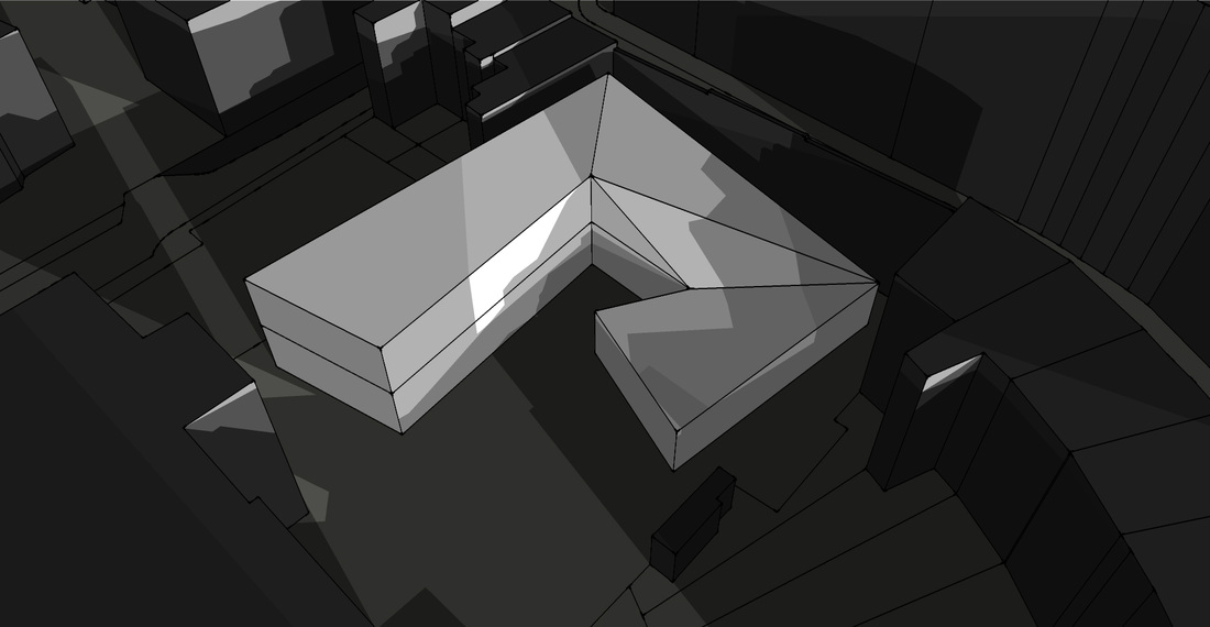 June 22, Concept 1.. 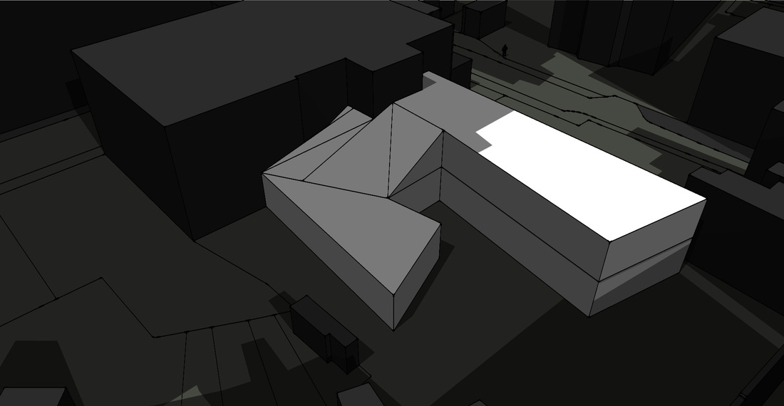 June 22, Concept 2.. 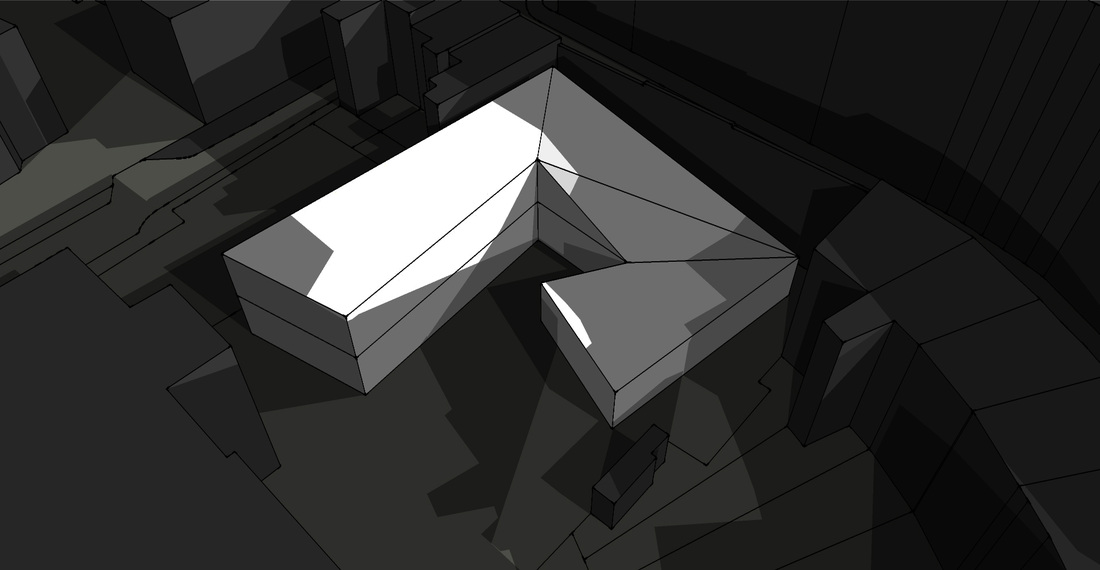 March 22, Concept 1.. 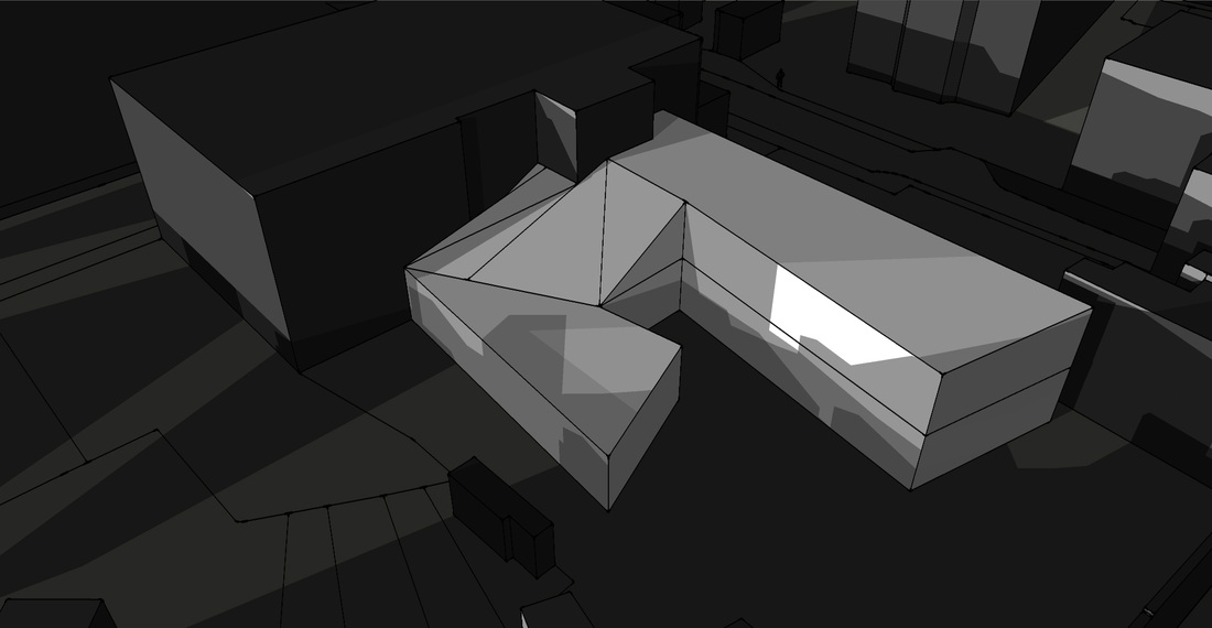 March 22, Concept 2.. 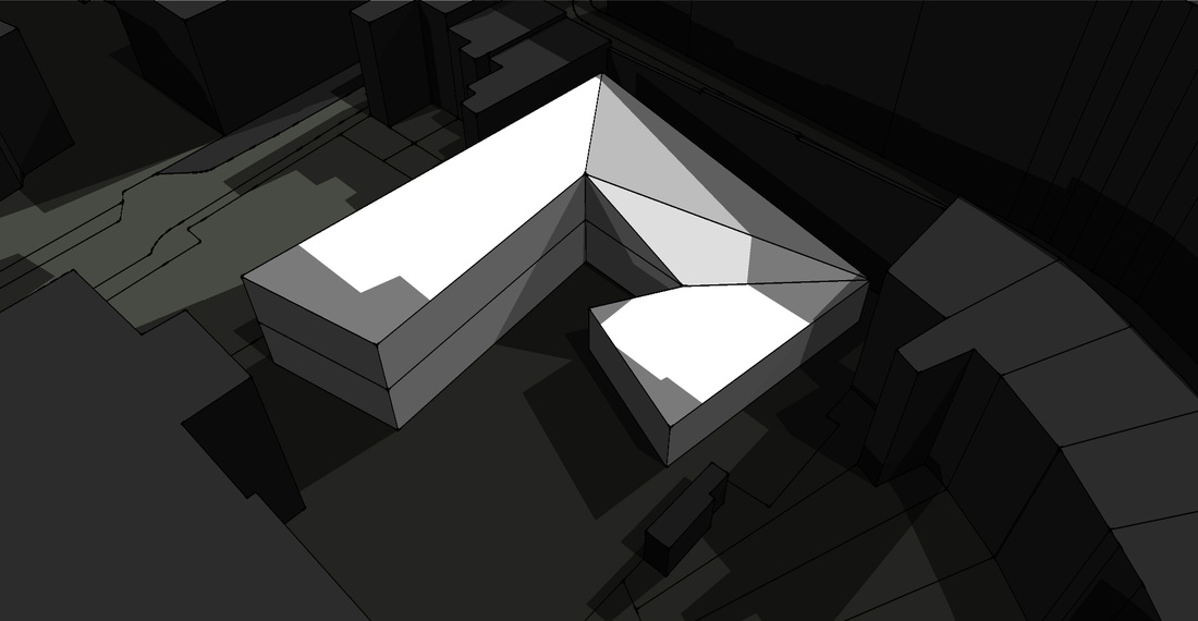 Dec 22, Concept 1.. 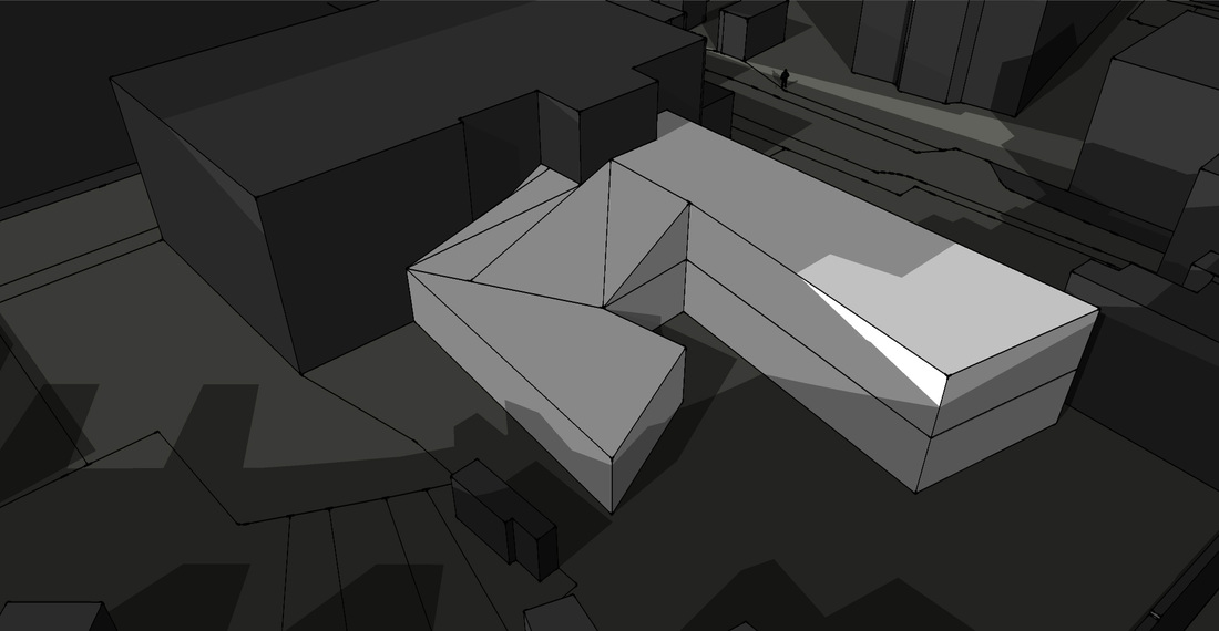 Dec 22, Concept 2.. Overall I felt that concept 1 receives the most sunlight compared to concept 2. As you can see even though at certain periods of time the concept 2 may receives sunlight, overall I felt that concept 1 receives the most concept sunlight.
However because of the overall form of the building there's certain parts of the building which receives more sunlight that others, however my plan in the south facing elevations where there most sunlight. I am planning to place the big workshop spaces because the spaces are very large and this is where i think natural sunlight is most essential. At places where there isn't alot of sunlight i am planning on using this spaces for lecture theaters as they don't require a lot of sunlight and tend to remain dark due to the activities going on in there. However another thing which I realised is that some parts of the roof receive constant sunlight so these will be places where I will try and incorporate as many sky lights as possible to take advantage of the subnlight. Thise has been a very activity as it actually allows us to start thinking about where certain rooms would be most appropriate and also helps gives us a general idea in how we can persure other systems, such as passive systems. Active Systems
- These systems implement alot of different technologies to help collect, convert and deliver energy - These systems use Wind, geothermal and bio energy - Solar collectors will be placed on the roof and south facing facades which can be sued to heat water, air and can be used to generate electricity - However one of the problems with active systems is the fact that they have to inspected and maintained every so often Active Wind Systems - UK has 40% of the European wind resource - so crucial to try and make the most of it. Power generated by: - Single turbines, which can be for domestic buildings - Small clusters - Wind farms - Very effective when used alongside PV panels, as in winter the turbines will be using the wind energy and during summer the PV's will be using solar energy - The forces on a wind turbine are incredibly high, which requires alot of structural work - A standard output from a turbine with a 5m diameter is 125 Watts peak. Active Bio-energy Systems - Biomass is a system which uses plant and animal matter - Harvesting biomass through the use of crops, trees or dung which can generate heat and electricity There are two main ways that these can be converted either through: 1. Combustion - Combine heat and power very efficient system in creating electricity and heat together 2. Anaerobic digestion - Organic wastes digested under anaerobic conditions. Heat pumps - helps generate heat which is generated from water sources such as a river, ground or waste water. Flat plate Collectors - heat from the sun which is then transferred into air or liquid that passes through a collector Evacuated Tube Collectors - Capable of supplying solar heated water at high temperature for residential purposes. 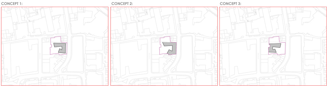 These are what my plans looked like once I drew them up on AutoCAD Concept 1: 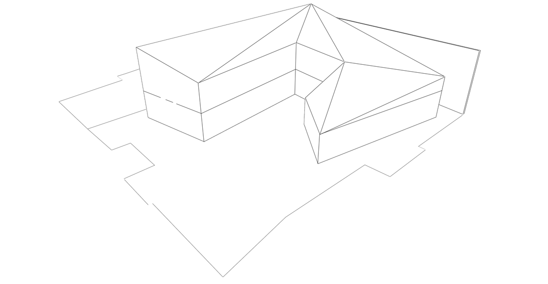 Concept 2: 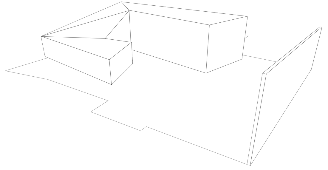 Concept 3: 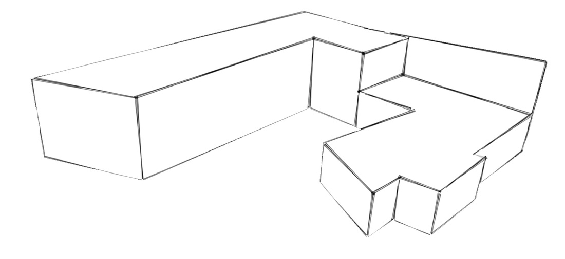 I then developed the concepts further in Sketchup by creating 3D Models. One of advantages of doing this is that it helps give the overall forms of the concept. After talking to Peter we decided concept 1 and 2 were most successful. So i will develop these further soon :)
Conceptual sketch of overall building..
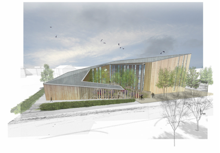
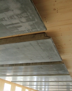
So I was looking around on the internet for a few inspirations and came across this project, which is the Woodland Trust HQ designed by KLH UK. The reason why I found this project so inspiring is because I felt the overall form was fascinating. It plan view it is quite unique but in section and elevation it is very dynamic, how the roof slopes from three floors to one floor, whilst creating this courtyard space within as well. 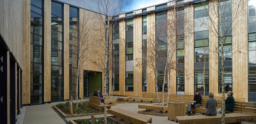
Elevation of courtyard space..
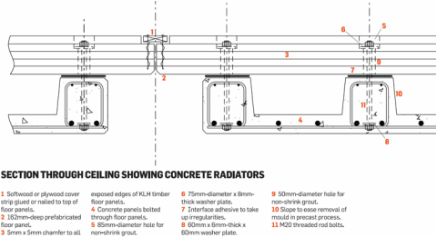
Another aspect of this project which I found interesting was the technology behind it, they used pre-fabricated concrete panels. See one of the problems with a complete timbered based building is trying to achieve the thermal mass of a concrete based building. However these 'pre-fabricated concrete panels' allow timber based buildings to reach the same thermal mass as concrete buildings.
To find out more infortmation about this building please read the following artcile: http://www.bdonline.co.uk/concrete-panels-boost-thermal-mass-at-feilden-clegg-bradley%E2%80%99s-woodland-trust-hq/3160542.article 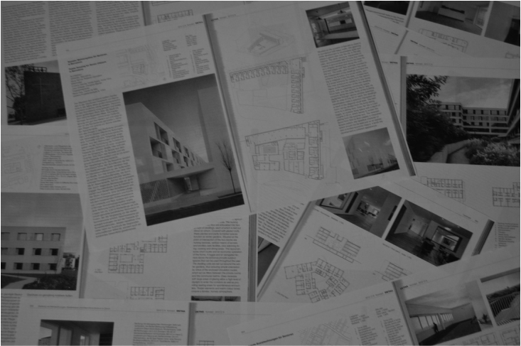 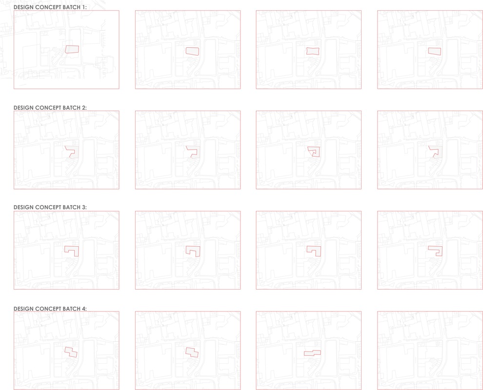 So today I decided to visit the library again to get some inspiration from the Detail magazines. So after spending after spending an hour there I found a projects which I was interested in, so I photocopied the pages which I was interested in so I could study them in more detail. So after studying the different projects I found in the Detail magazines, I started drawing a few examples of potential designs I could use for my own project. I then went and saw Peter and we agreed that Design concepts batch 2 had the most potential, so I will develop this further :)
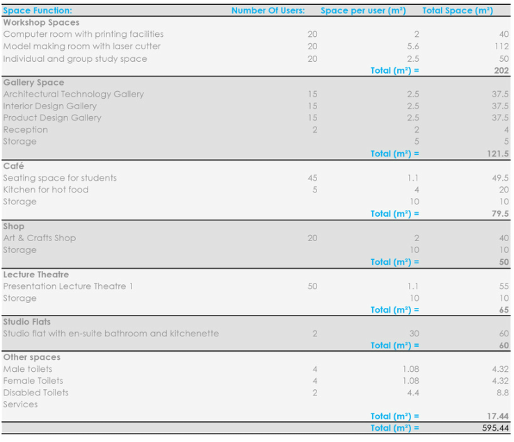 PDF of Space Listing spreadsheet.. So after writing up my own brief specifying the users for the buildings we then had to specify room sizes to ensure our buildings are appropriate sizes. So to do this I used a book called 'Metric Handbook Planning And Design Data'. 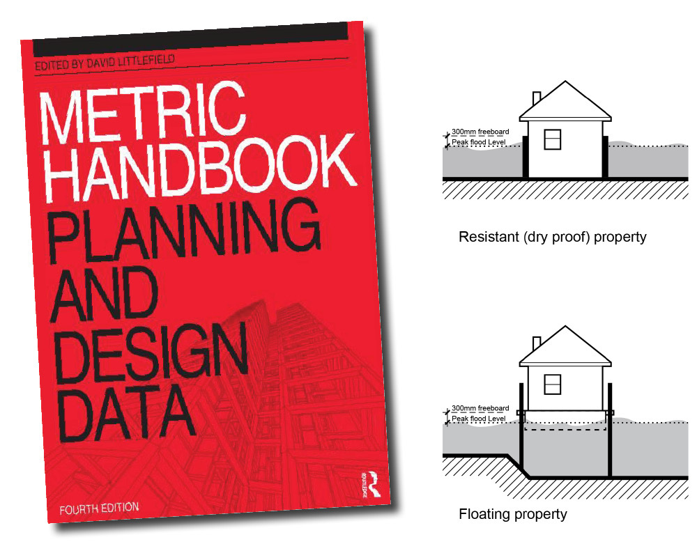 The amazing thing about this book is that it provides standard sizes for room with specific functions. As we already know roughly how many people would be using the rooms within the building, we can times this by numbers provided through the book to ensure the room sizes are accurate.
So we were asked to create a brief which specifies the users for our buildings, which then helps us decided on the room functions. So here is my brief:
The building is to provide for 3D Design students, this will range from students studying courses within Architectural Technology, Interior Design and Product Design. As the building will have to provide for three different courses the spaces within Vulcan works will therefore have to be multifunctional to meet the requirements of three different courses. For each course there will be roughly 15 students, therefore altogether there will 45 students. Workshops Some of the functions these room will to provide for are the following: - Computer lab - Printing - Model making – strong adhesive/glue may require extraction - Laser cutting – require some form of extraction - Gallery Gallery space Gallery space is to be used to exhibit the works of the students from Architectural Technology, Interior Design and Product Design. So they will need flat boards to attach work too and also a stand to put models on. The Boards will have to allow for a minimum of 4 A1 sheets of paper, the stand is to be glassed to protect the models. Small Lecture Theatre The Lecture Theatre is to accommodate for all 45 students. Café Cafe is to cater for all 45 students. Small shop Small shop is to sell stationary, other equipment such as card, adhesives, etc. – which is only open for students. 4 Studio flats 2 studios flats will be for guest visitors, 2 will be available to students. These flat will include a bedroom, lounge/dining room, kitchen, WC with a shower. So today I received my grade for the Pen-tech project, I got an A- which in all honesty I wasn't expecting it. Even though I was working on this project continuously for a month. There was a few sleepless nights - then again that's just the student life!
On the submission day I was all over the place because I didn't sleep that night, I was tired and also nervous at the same time. 10 minute things were nearly taking me an hour to carryout, at the same time I was panicking as I felt that I wouldn't be able to get everything done. However I was incredibly happy with the overall grade and the work I managed to produce. It was a very interesting project but also quite difficult at the same time because it was really the first project which involved us having to carry out structural calculations, for example beams sizes, etc. For that reason I really did enjoy this project because it was definitely challenging which also taught me alot. Now we have a week to chill before we get given the brief to our next design project, I hope you enjoyed reading about this project :) 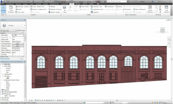
Image Capture of Vulcan Works facade in Revit..
So this week during CAD class we started creating and modifying sweeps, it was really interesting as you can pretty much design any sweep you want. As there's alot of decorative detail on the Vulcan Works facade we well be asked to do this during our CAD assignment.
I also managed to put a few windows in by just modifying the standard windows already which come with the Revit Library. So today in Tech & Services today we looked at direct gain and heat loss, and we have to integrate this into our design project. It was an intense session but I'll try and break things down to help make sense out of it all.
There are two main categories of renewable energy system: - Passive systems - Active systems Passive System - So this is when you gain and store solar heat and light whilst using as less very little technology as possible - So these systems work through the floor plan, building geometry and materials which collect, store, retain and distribute solar energy - The main aim of these technologies is to ensure that in winter buildings can get sunlight and in Summer there isn't too much sunlight entering the buildings - We try and keep most of the windows/glass on the south side of the building, and keep windows to a minimum on the other faces of the buildings - Whilst thinking about solar energy, we also try and try and bear in mind natural ventilation - Try and build 'thermal mass walls and floors' which help store heat in summer periods and in winter this energy can be used again Active System - These systems implement alot of different technologies to help collect, convert and deliver energy - These systems use Wind, geothermal and bio energy - Solar collectors will be placed on the roof and south facing facades which can be sued to heat water, air and can be used to generate electricity - However one of the problems with active systems is the fact that they have to inspected and maintained every so often Passive Solar Design This is when buildings are designed in a manner where they are able to collect energy from the sun and then re-used for heating and lighting, such buildings are able to: - Collecting energy - Store energy - Distribute energy Multi-layers Approach This approach helps reduce heating demand through: - Form - Insulation - Drought stripping So I now need to think of ways where I can introduce different passive and active technologies into my own design project, so I'll try and keep you guys updated :) 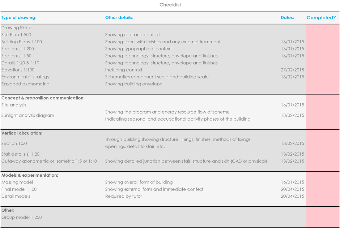
A database/checklist I created using Excel..
So a few of us asked Peter how many pages he's expecting our final portfolio to be, he replied "120 pages". At first we honestly thought he was joking, then we remembered Peter doesn't joke about. The main reason why we thought he was joking because we're so used to creating portfolios with rough 30 pages, and he's expecting 4 times that amount.
In all honesty I just don't think I've really spent enough time on an idea due to the amount of other work I have for other projects, but anyways I can't start making any excuses. Except learn from what I've been told about my previous concepts, and start the project with a fresh mind. So after reaslising that my previous concepts aren't going anywhere and I'm slowly loosing time, I decided to create a database to manage my time more efficiently. So I set out the main tasks and dates with when they should be done, but I can also check off whatever I complete so im able to look at it and see where about I am with the project. 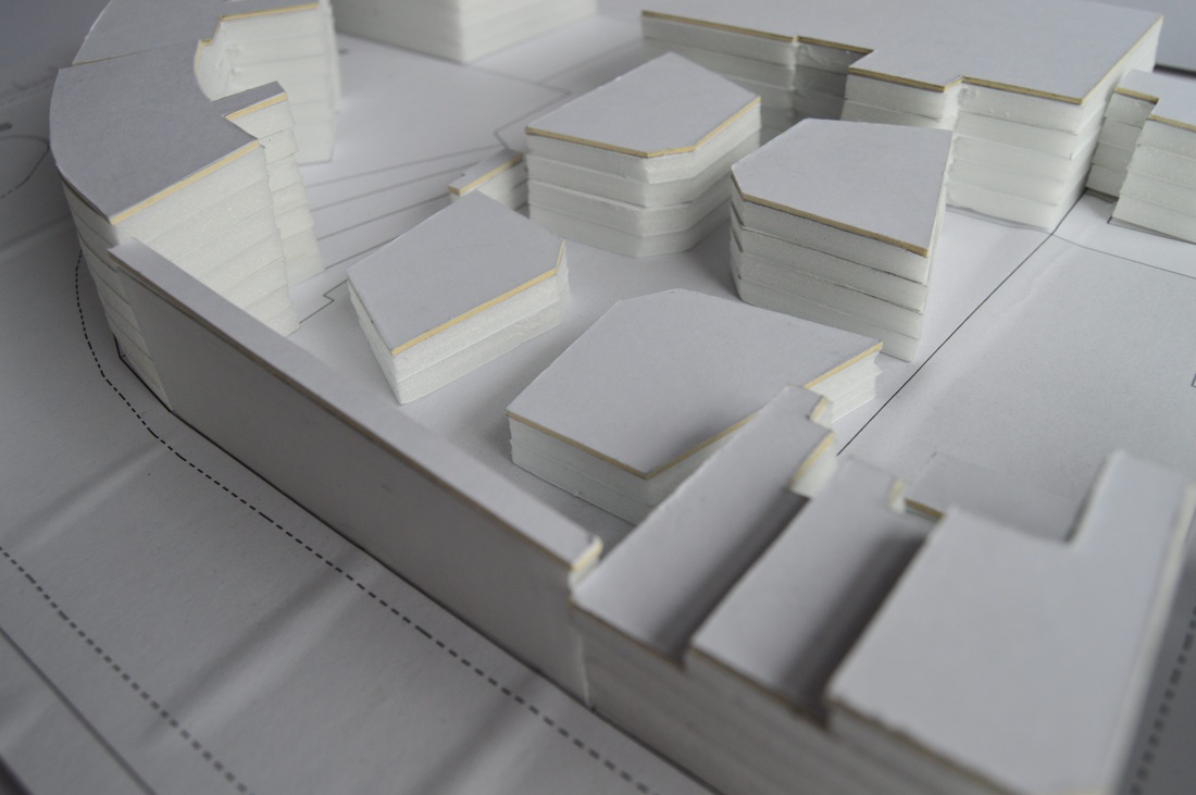 Massing model for developed concept.. So after the feedback I received last week I made a few changes to that particular concept. So instead of one whole building i divided it up into 4 different buildings. I thought it would be interesting to make the building different sizes, so two of the building would only consists of one floor and the other two consisting of two floors.
However after talking to Peter again he wasn't crazy about the idea, although it was better than the initial concept. He just felt that it didn't really work, and after listening to his points of view it did make a lot of sense. So its now back to the drawing board for me. |
Recent PostsBusy, Busy, Busy! Categories
All
Archives
January 2016
|
 RSS Feed
