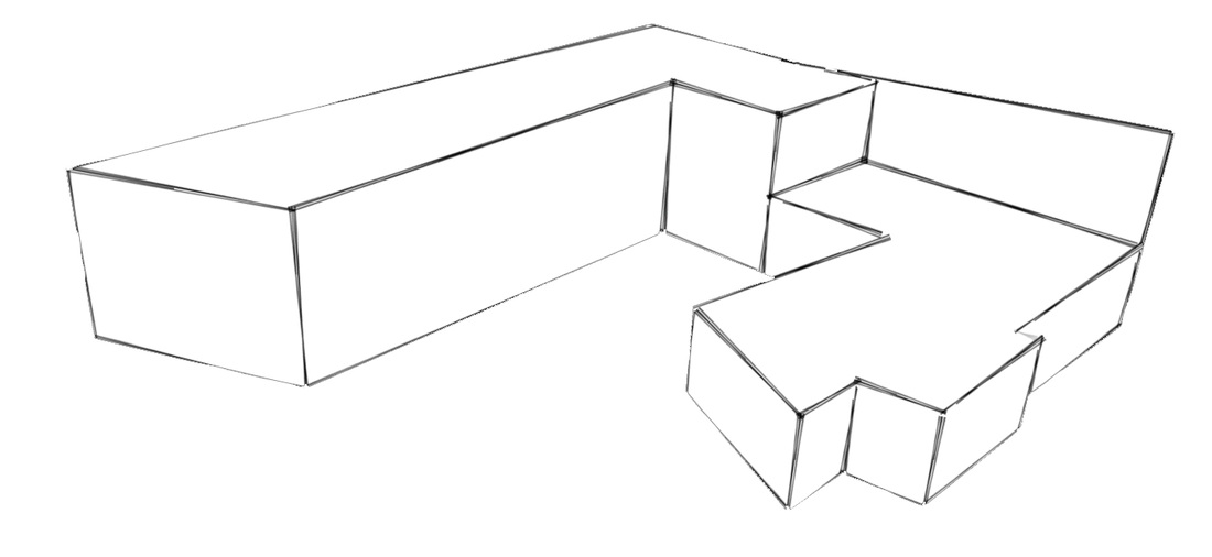
For my framed structure I wanted to use Glulam columns and beams, the main reason being because I wanted to try this method as I haven't previously used it.
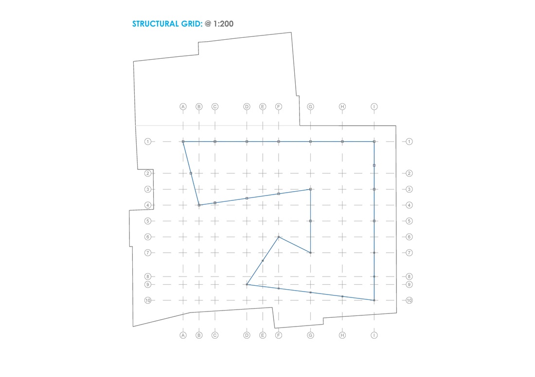
- A structural grid of 5 x 5 meters
- Columns where the building will be at 2 stories, they are: 350 x 350 mm columns
- Columns where the building is only 1 story, 300 x 300 mm columns
- A structural grid of 5 x 5 meters
- Columns where the building will be at 2 stories, they are: 350 x 350 mm columns
- Columns where the building is only 1 story, 300 x 300 mm columns


 RSS Feed
