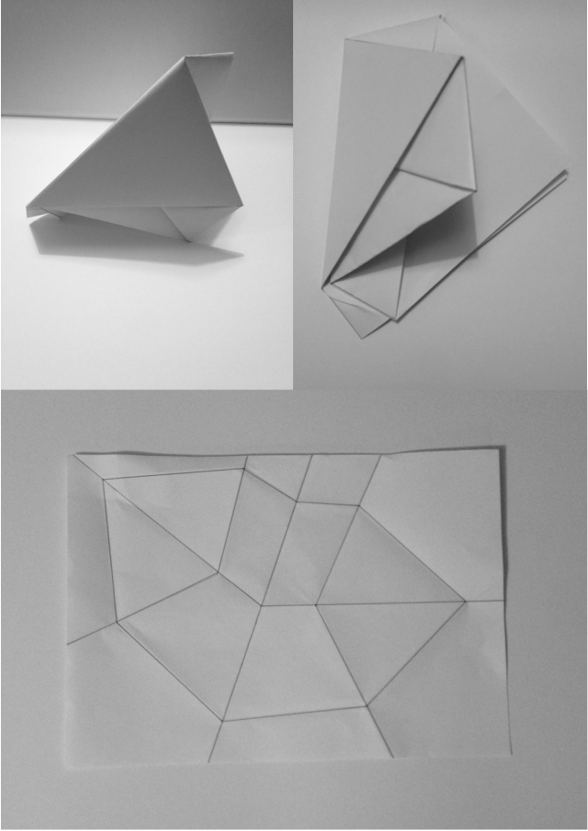
Folding Concept 1..
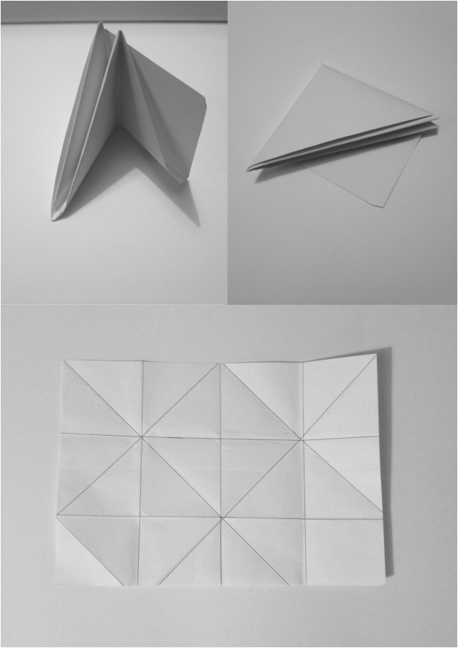
Folding Concept 2..
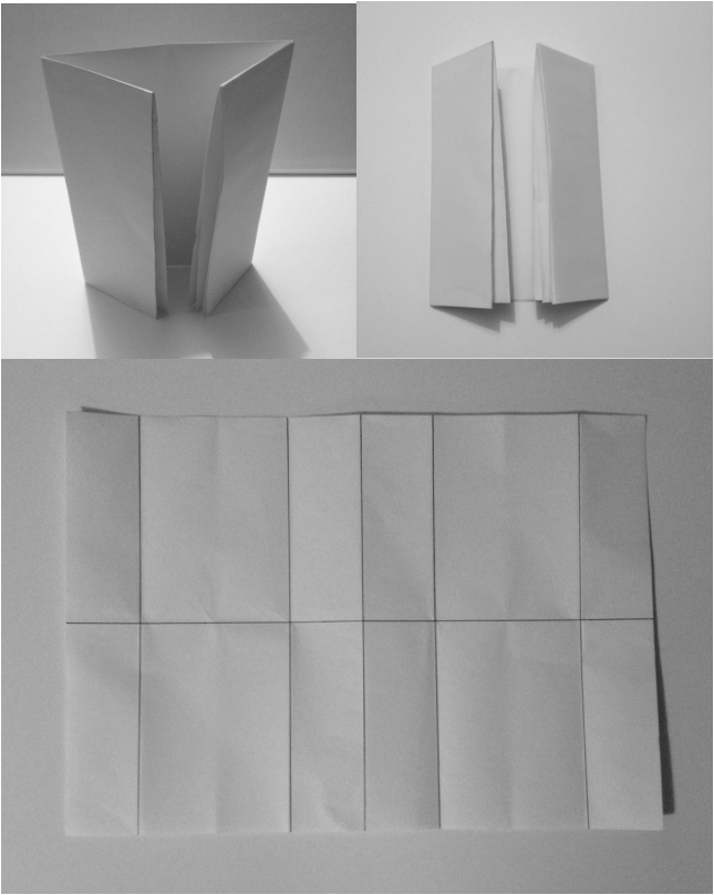
Folding Concept 3..
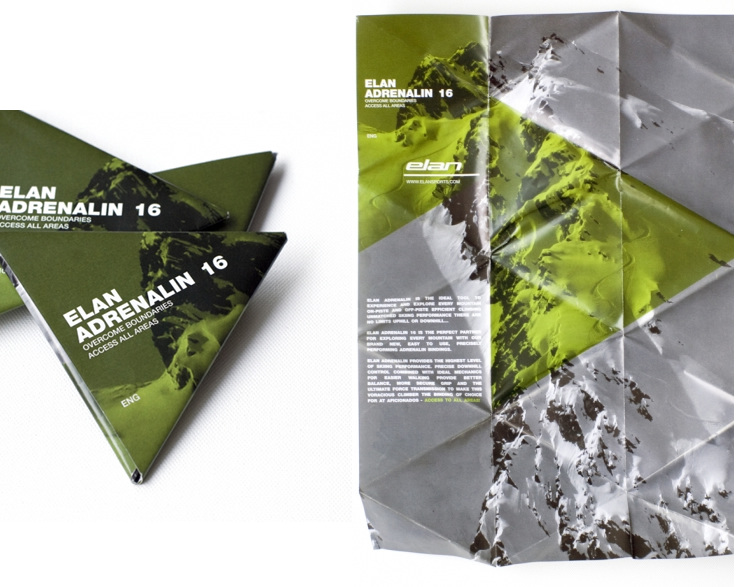
Out of all 3 concepts I did prefer concept 1 as I liked the overall form of the leaflet and felt it was most interesting, however I reaslied that I would struggle to include images and text, and the folding didn't really flow.
I do like concept 3 even though its very simple I feel it is quite elegant and could look quite professional, I wouldn't have a problem inserting images or text as it consist of a very simple layout, so I think I will go with this concept.
I do like concept 3 even though its very simple I feel it is quite elegant and could look quite professional, I wouldn't have a problem inserting images or text as it consist of a very simple layout, so I think I will go with this concept.


 RSS Feed
